I am a graduate student studying computer engineering, and I’m working on a project to diagram and explain what design choices make the Blinks work. Has Move38 posted the hardware schematics anywhere? I’d also be interested in what protocol is used for the infrared communication.
Hi @splatt,
Here’s a link to the PCB schematics along with a theory of operation. GitHub - bigjosh/move38-blinks-pcb: PCB and HAL for production ready blink tiles
@bigjosh wrote a really nice breakdown of one really neat aspect of the design for the display on Blinks, the charge pump, and it is here. He also demonstrates it in this video that I really enjoy.
While I think there is likely some fun to be had in reverse engineering a Blink, feel free to reach out with any questions ![]()
best,
jb
p.s. across the different Kickstarter campaigns, I tried to document and share much of the process, and from a design/technical perspective, likely the first KS campaign here has a number of relevant (and admittedly verbose) posts between #10 & #20.
1 Like
The IR protocol is by far the most complicated part of the blinks design.
The physical layer uses very short flashes of light on the transmit side. The spacing between these flashes encodes the data.
On top of this physical layer, there is a packet layer. Here is a sample 2-byte packet (typical packets on running blinks are usually longer) where each pulse is a flash of the sending LED…
On top of the packet layer there are other layers that add checksums and stuff like that. The first byte of the packet is always a packet type, and packet type bytes chosen for maximum hamming distance.
All of these decisions are driven by constraints on the receiving side, which uses the same LEDs. The receive side is very complicated, so LMK if you have any specific questions.
1 Like
Interesting!
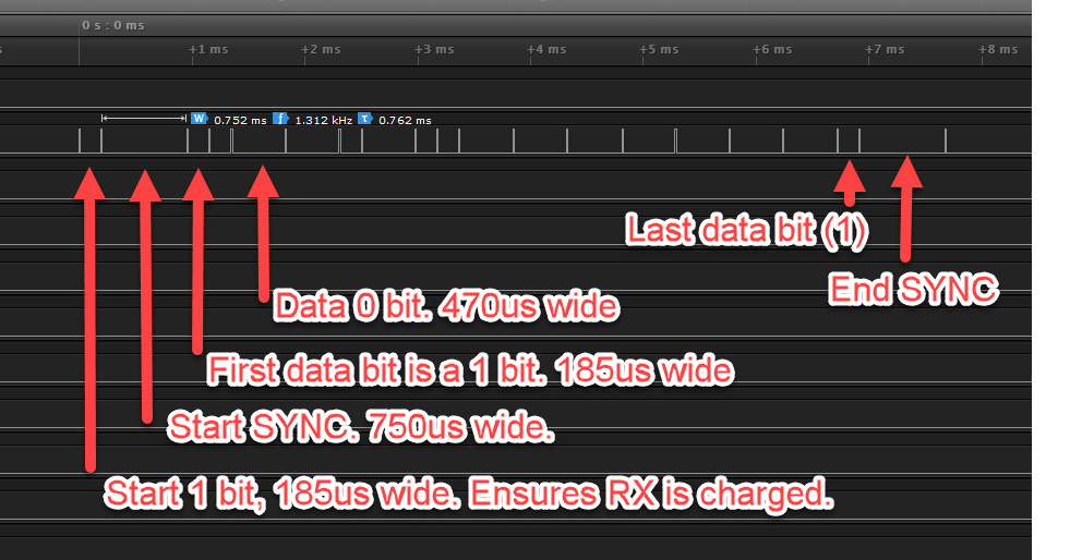
- I’m assuming that sides cannot transmit and receive at the same time. How does the blink know whether a side is to transmit or receive? Just which ever blink initiates the transmit first? (“Ensures the RX is charged”)
- What was the design decision for the infrared LEDs? Power?
- Is this a new protocol that you designed to work around how the LEDs transmit/receive, or was it existing?
- And how do the clocks synchronize? I’m assuming because of only 1 data “line” that only data is being transmitted between blinks, but is the clock also included in the data?
Correct, you can not physically TX and RX at the exact same time.
There are several layers of protocols to handle this. At the lowest level, as soon as a blink sees a flash on an LED, it blocks transmits on that LED until either it has gotten a full packet or there is a timeout.
There is still a very small chance that two LEDs could transmit almost at the same instant. To avoid this, there is a “ping-pong” protocol where the two blinks on either side of a link are constantly exchanging short link packets. It is complicated, but this ping-pong assures that there is never a collision for as long as the link has a steady connection.
To cover the extremely unlikely case where two blinks are first put next to each other and they both happen to flash their first flash at the exact same moment, there is a random timeout to between consecutive “link probe” packets that will ensure they eventually (almost assuredly on the next cycle) de-sync.
Which blink gets the first flash across the link when they are put next to each other is random. Both blinks will always have their LEDs “charged” all the time except when they are transmitting or exactly the split second after they have seen a flash. That first TX start bit is there to initially discharge the RX LED so it gets charged again before the sync pulse. It is complicated how/why this works.
LED selection is driven by…
- How fast they discharge when they get a flash (related to sensitivity and capacitance)
- Optical entrance/exit angle. You want narrow enough to reduce the light noise from other sources other than another matching LED directly pointing into it.
- Cost and availability (there are 6 of these on each blink!)
The speed of discharge is very import because it limits both your maximum data rate and also indirectly your noise immunity since the faster you can RX flashes, the faster you can TX flashes, and so the time between flashes is shorter, and the shorter the time between flashes, the lower the integral of the ambient light collected between flashes.
This protocol is specifically for blinks - and even specifically tailored to the particular LED parameters.
Sort of. This protocol is sort of like an async protocol like RS232 where it is time between events that matters so there is not a a clock per se. You see a flash and then you start counting until you see the next flash. If the time between the two consecutive flashes is between A and B then it is a 1, if the time is between B and C then it is a 0. If the time is less than A or more than C then there was an error. (A and B are on the order of 100’s of microseconds in the blinks protocol).
2 Likes