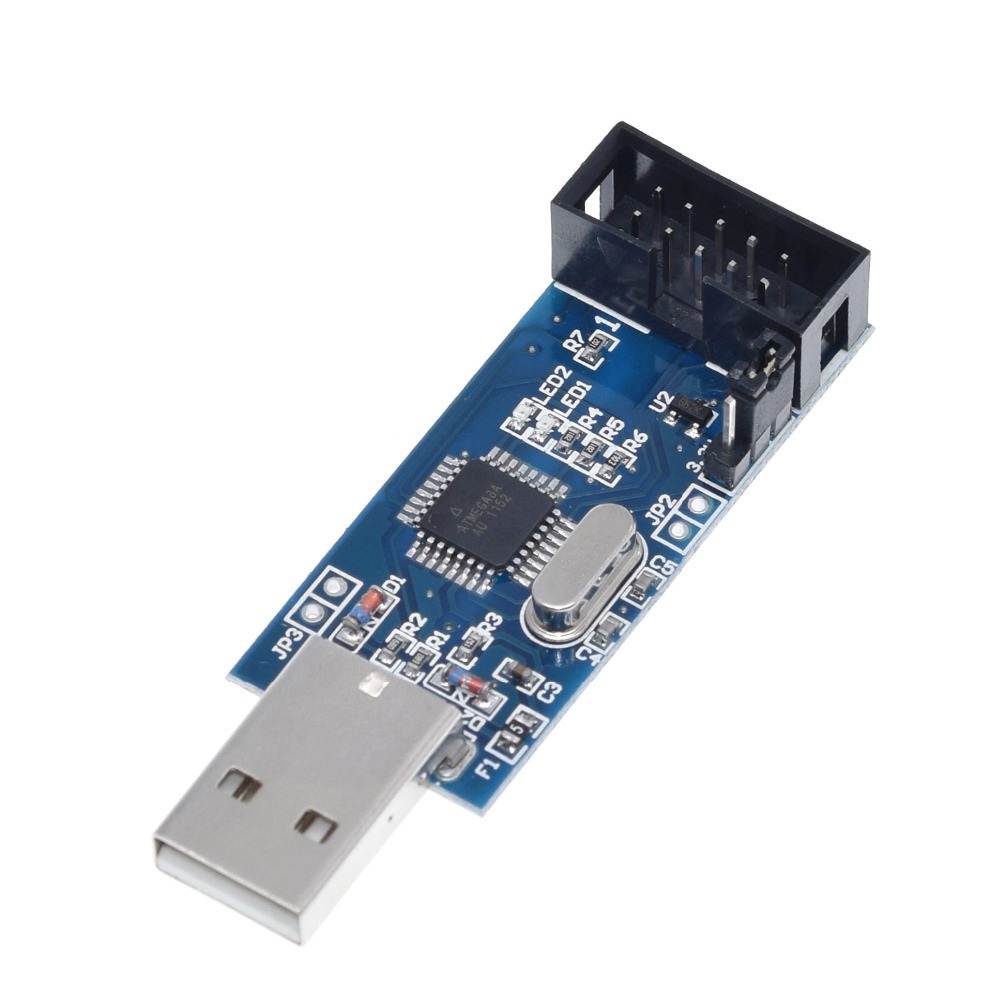
Did your Move38 dev tools get lost, break, or would you like to develop for Blinks without ordering dev tools from Move38, you totally can  . To make it nice and easy, here are the 2 items that are really necessary for uploading code to Blinks:
One plugs in as the USB programmer and the other allows you to contact the programming port (ISP) on the Blinks circuit board. The pogo adapter does require some soldering that is worth watching the youtube video of how to do it.
The Move38 comes with our own pogo adapter which has proven less prone to breakage and some additional tools to make things like removing a Blinks protective sticker or a 3D printed jig or case to keep things protected on the go.
There are many alternative ISP programmers that will work with Arduino and therefore Blinks. We are often times able to troubleshoot common hardware quicker than something we don’t actively develop with ourselves.
OOOH I almost forgot, one fun DIY option is to use an Arduino as an ISP programmer. One of the best experiences I had in 2007 was building a breadboard Arduino by myself, it most likely lead to a foolish confidence that something like Blinks were possible.
Happy hacking!
2 Likes
I like the fact that the dev tools can be hand made with multiple choices.
While we wait for the Kickstarter campaign to finish and have news about the improved developer kits, I´ve been doing some research on how to improve the tools for an easy connection
I´ve seen in some videos a kind of clip to atach the pogo pins to the board, also a case to protect the programmer so I think that a good idea can be to have booth at the same time!
As you can use any AVR programer you want, even an Arduino board (and it should be kind of an easy plug & play) i found some AVRs with a full size USB (so you dont mess with cables). On the side of the pogo pins, I´ve found a really nice clip with 6 pogo pins that is pretty easy to build:
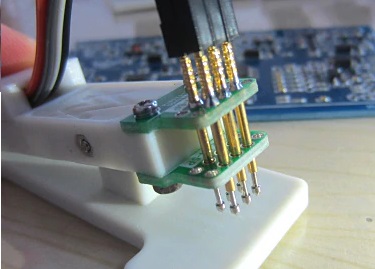
If we mix both things together, and add a nice stand for the Blinks, we can have a nice 3D printed programming tool. You can have a space carved on the plastic clip that prevent the Blink from moving, and the pogo pins on top as a clip without touching or holding anything.
I´m planing on doing this design for myself and 3D print the case with the spring and the pogo support. I have time until Blinks arrive!
What do you think?
2 Likes
I´m still working on this idea. I just get a USBasp from a local store and want to try some crazy solutions with my 3D printer.
One of the solutions is the previously posted with the pogo pins and the 3D printed clamp.
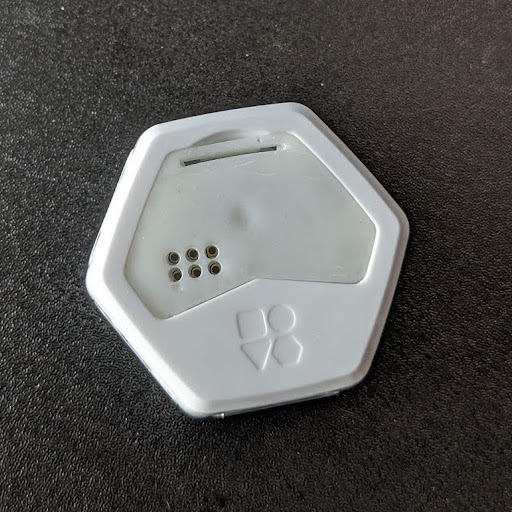
My second crazy idea is to attach the pogo pins to a battery cover, so you just take out the blank battery cover and put a modified battery cover attached to the programer.
Is there any option to get the 3D model of the battery cover to 3D print one and try this crazy idea?
Also this make me think on another question, how can we get spare parts if we just lose a battery back?
As I said previously I have plenty of time until the Blinks arrive so i want to try some things before =D
Here’s a link to the 3D model of the Blinks battery cover
At the moment, the best way would be to ask  . We’ll be sharing some new offerings soon that address this as well.
Wow!! That was fast!
Thanks for sharing the 3D model in thingiverse, with that I can try some crazy ideas!
I will post the results!
2 Likes
Tried to 3D print the model, it works perfectly using supports but is very fragile, i don´t think it can survive more than 2 uses using it as a dev tool. The closing tab is too thin.Definitely injection mold plastic is better  Anyway if in the future there is an option to get spare covers I will try it cause once printed i realized it can be a pretty good tool.
I also tried to find a local store with pogo pins but it looks like pogo pins are not popular in my country  so just ordered them on internet, I can´t finish anything, I have to wait one month!
I already printed a case for the USBasp, i just need to 3D model the other part 
1 Like
A note on the AVRasp versions of the programmer. The programmers with USB A male attached to the board tend to be be AVRasp boards, which totally work with Blinks, but in my case, required a bit of work first (and unfortunately, required having another programmer on hand).
The Dev branch of the Blinks SDK now supports the AVRasp (thanks @bigjosh)!
The one that I ordered on Amazon for $7.99  did not support the lower speed upload that we are using for Blinks and threw this error message when used (the actual issue is the warning, the error is a direct result of the warning in this case):
avrdude: Version 6.3-20190619
         Copyright (c) 2000-2005 Brian Dean, http://www.bdmicro.com/
         Copyright (c) 2007-2014 Joerg Wunsch

...

         Programmer Type : usbasp
         Description     : USBasp, http://www.fischl.de/usbasp/

avrdude: set SCK frequency to 187500 Hz
avrdude: warning: cannot set sck period. please check for usbasp firmware update.
avrdude: AVR device initialized and ready to accept instructions

An error occurred while uploading the sketch
Reading | ################################################## | 100% 0.00s

avrdude: Device signature = 0x010307
avrdude: Expected signature for ATmega168PB is 1E 94 15
         Double check chip, or use -F to override this check.

avrdude done.  Thank you.
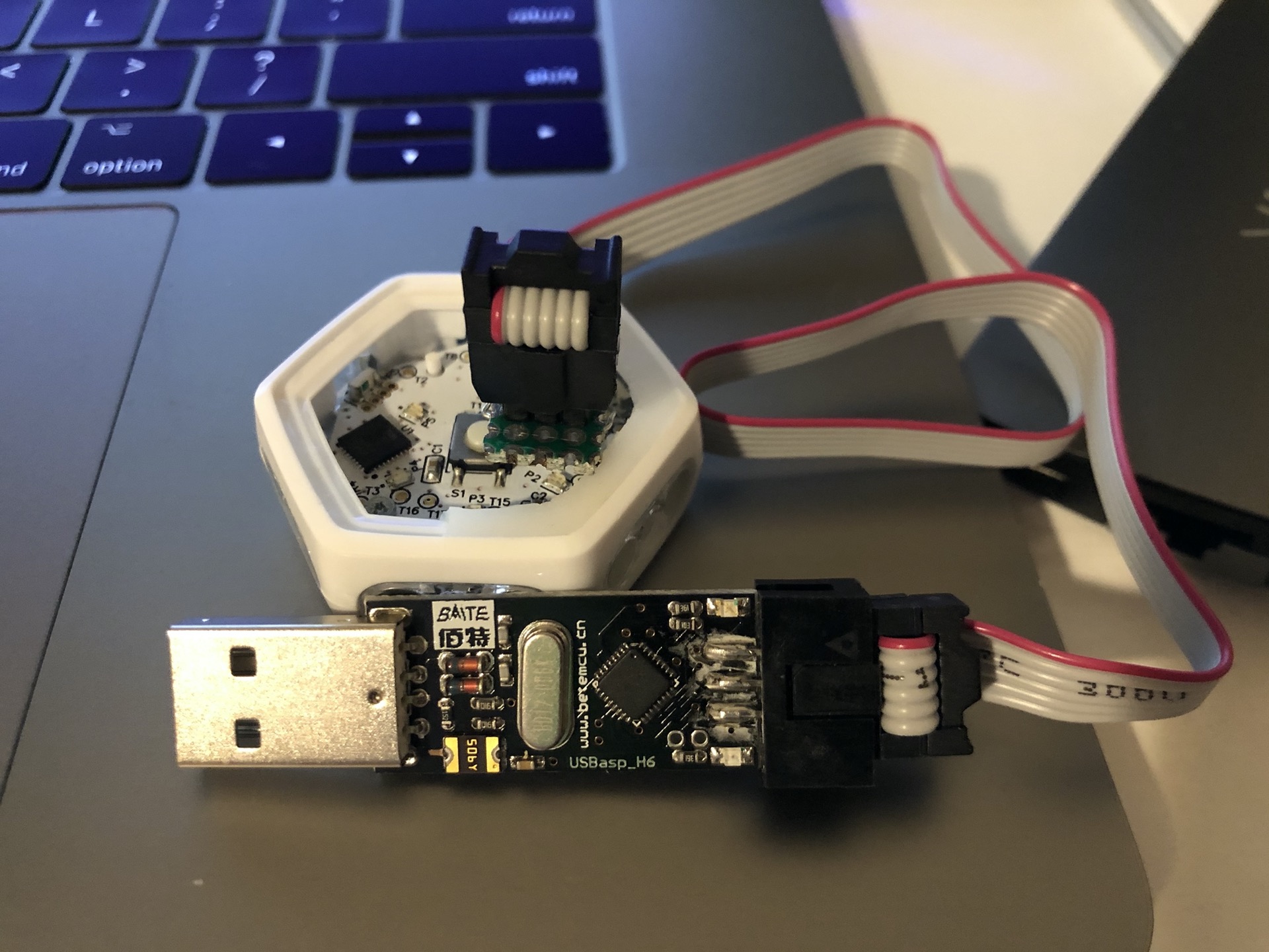
and the solution for this is to flash the AVRasp with updated firmware like the following tutorial here. Worked like a charm for me, I needed to simply jump the single connection you can see in my photo available to jump and it worked. The funny thing is that I used my Blinks Dev Kit included USBtiny to perform the firmware update, but that’s a cool feeling in itself.
While we find it easier to support everyone on similar hardware, we don’t discourage using alternative means and this is a great alternative for those looking to practice hardware hackery.
2 Likes
WOW!
Nice you tried it! I will try to update it with an actual Arduino board
Edit: Done and working! Thanks @jbobrow !!!
2 Likes
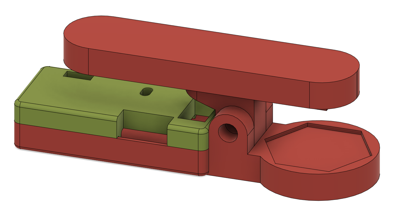
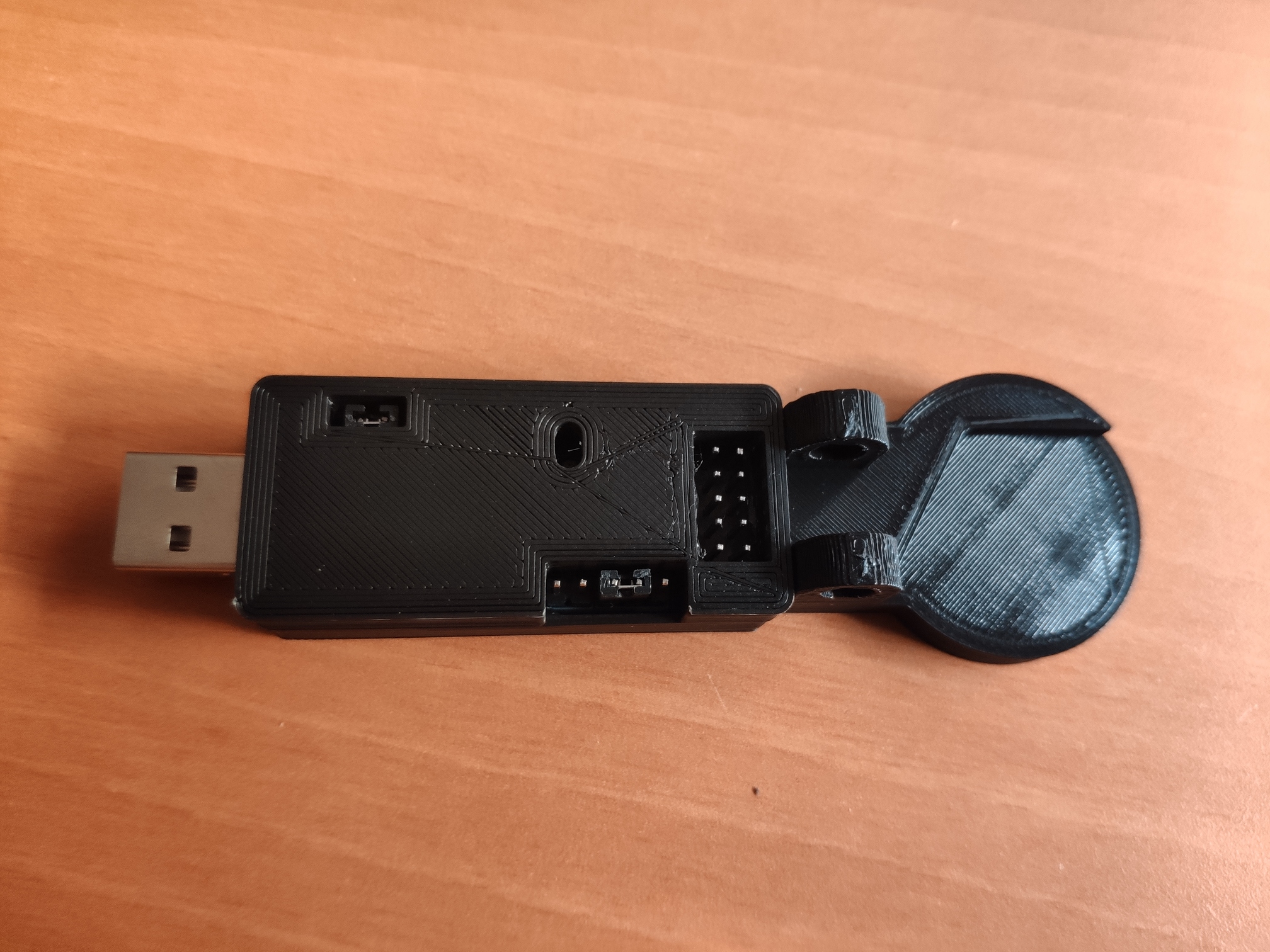
Well, here is a sneak peek of the usb case I´m doing for the AVRasp.
Is a 3 piece case, no supports needed to print it.
I can´t finish it propperly until having one blink to take some measurements (mainly to align the pogo pins to the base) but I think you can get the idea.
The top part have a small space to put cables from one side to the other.
The idea is to have a compact usb plug & play programmer inspired in a clothespin:
3 Likes
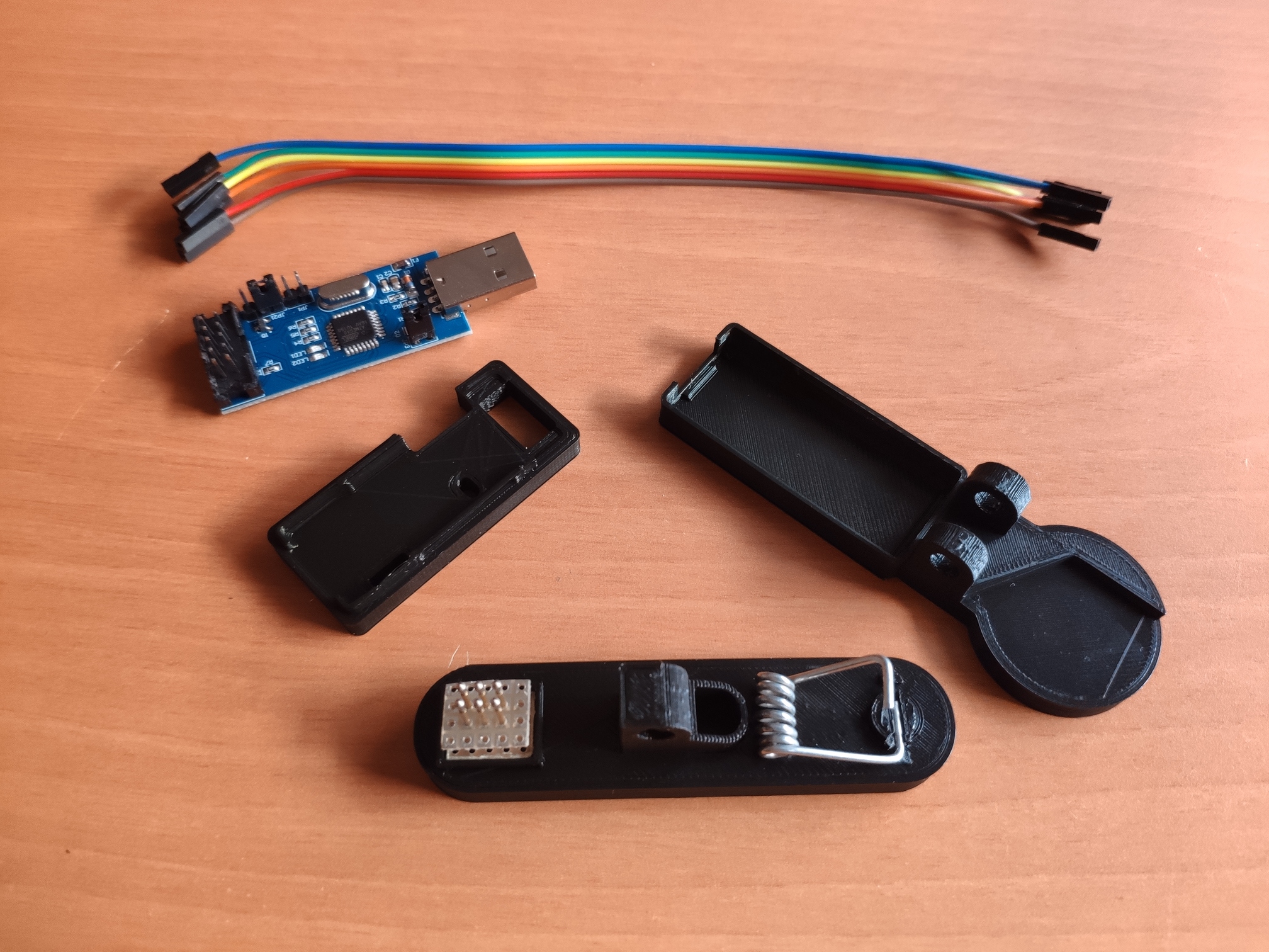
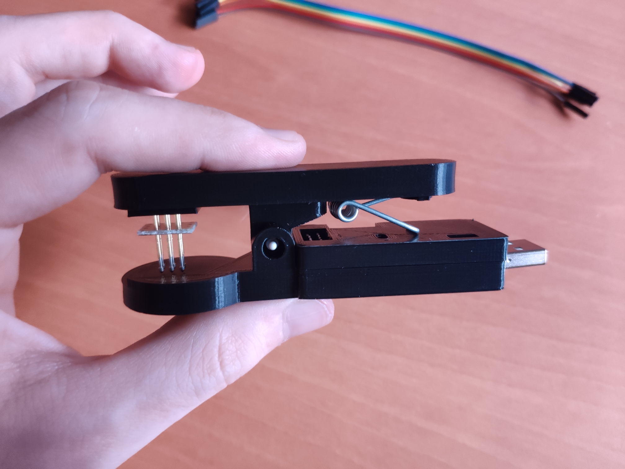
Here is a first run of my developer clothespin 
Still working on it, but I must say it works better than expected 
EDIT:
Redone some parts and tried a second print for 2 of the 3 parts. Now the metal spring is safely accommodated on the case
Everything seems to work perfectly.
Waiting blinks for the second print of the bottom part once I have real measurements.
3 Likes
That is so awesome! Nifty concept and looks like it would work great especially with a laptop setup. Great work!
1 Like
Time to resurrect another dead thread! I just printed @jbobrow 's battery cover after modifying it with some holes positioned after some careful measuring.
I printed it using Tough 4k resin on a Form3 printer. It should withstand repeated removals… though I think I may remove the hook on the bottom as you really don’t need to attach the back… it’s just for alignment. The only real issue is that the pins on my programmer get caught on the edges when I remove it. I may have to create a box around the holes reaching most of the way to the board to fix this.
I’m also waiting on a replacement programmer since one of my pins broke so I can’t actually tell if it’s doing the job… but at least it looks like it’s going to work. 
1 Like
 . To make it nice and easy, here are the 2 items that are really necessary for uploading code to Blinks: